Soil moisture sensors are crucial tools for optimizing irrigation strategies, boosting crop yields, and improving resource efficiency in gardening and agricultural settings. This article delves into the essential principles behind different types of soil sensors, exploring their operational mechanisms, advantages, disadvantages, and practical applications.
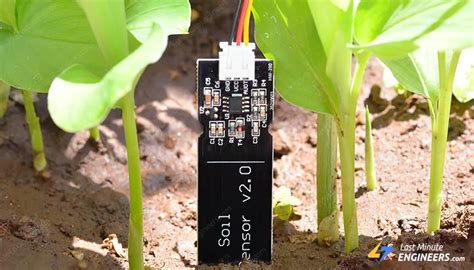
Capacitive Soil Moisture Sensors
Capacitive soil moisture sensors operate on the principle of capacitance, which is a method of storing electric charge. A basic capacitor consists of two metal plates separated by a dielectric material. The amount of charge a capacitor can store is influenced by the properties of this dielectric. In a capacitive soil moisture sensor, the soil itself acts as the dielectric. Water molecules in the soil have different electrical properties than dry soil, allowing them to store more charge. Consequently, as soil moisture levels change, the sensor detects these variations in the soil's ability to store electrical charge.
The working principle can be analogized to filling a cup with water. A dry cup (like dry soil) is a poor conductor of electricity. Adding water to the cup makes it easier for electricity to flow (like wet soil). A capacitive sensor measures this change to estimate soil moisture content, with higher moisture levels correlating to greater stored charge.
Advantages of Capacitive Sensors:
- Moderate Accuracy: Commercial capacitive sensors can achieve accuracies of 3%-5% after calibration for specific soil types and environments.
- Quick Response: These sensors measure the dielectric constant of the soil, enabling them to detect moisture changes within seconds.
- Durability: Their simple construction and insulated circuits, where electrodes do not directly contact the soil, lead to high durability and resistance to corrosion. Lifespans typically range from 1 to 3 years.
- Wide Compatibility: Capacitive sensors are compatible with popular microcontrollers such as Arduino, Raspberry Pi, ESP32, and STM32, offering great versatility.
- Multiple Interfaces: They support analog output, and some models also offer I2C or UART interfaces for seamless integration with various devices.
- Low Maintenance: While requiring minimal maintenance, periodic recalibration might be necessary in high salinity environments to ensure accuracy.
Suitable Soil Environments for Capacitive Sensors:
- Variable Soil Environments: Capacitive sensors accurately measure soil moisture even in soils with varying conditions, such as seasonal changes or areas with different drainage properties, as they do not require direct soil contact.
- Saline Soils: These sensors are relatively insensitive to soil salinity, making them suitable for use in saline soils. However, very high salinity or air-filled soil can still interfere with measurements.
Applications of Capacitive Sensors:
- Home Gardening and Indoor Plant Monitoring: Their wide compatibility makes them ideal for integration with Arduino or Raspberry Pi systems to create automated irrigation for home and urban gardens.
- Outdoor Farmlands and Greenhouses: Their cost-effectiveness, moderate accuracy, low power consumption, low maintenance, and high corrosion resistance make them suitable for continuous monitoring in fields and greenhouses, including those with saline soils.
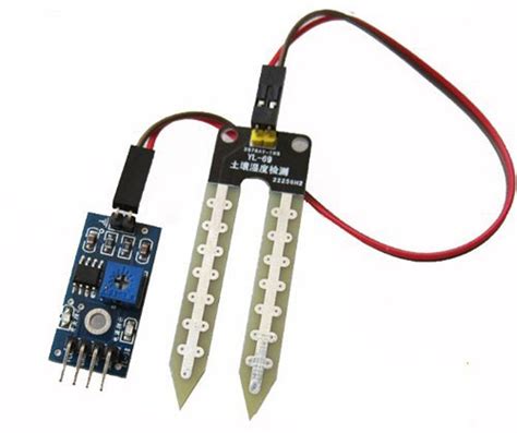
Resistive Soil Moisture Sensors
Resistive soil moisture sensors operate by measuring the electrical resistance of the soil. The fundamental principle is that water conducts electricity, while dry soil does not. The sensor works by sending a current through a pair of metal electrodes inserted into the soil. The resistance encountered by the current as it passes through the soil is then used to estimate the moisture content.
Imagine inserting two conductive rods into the soil. If the soil is dry, the current faces high resistance. Conversely, when the soil is wet, the current flows more easily, indicating lower resistance. The higher the moisture content, the lower the resistance detected by the sensor.
Advantages of Resistive Sensors:
- Low Cost: Their simple construction and lower manufacturing costs make them more affordable, suitable for budget-conscious projects.
- Easy to Use: The straightforward circuit design is ideal for beginners and quick experiments, easily integrating with platforms like Arduino or Raspberry Pi.
Disadvantages of Resistive Sensors:
- Low Accuracy: These sensors are susceptible to soil type and salinity, often exhibiting errors ranging from ±5% to ±10%.
- Slow Response: Data stabilization can take several minutes, making them less responsive to rapid moisture changes compared to other sensor types.
- Low Durability: The electrodes are in direct contact with the soil and are prone to corrosion due to electrolysis, leading to a shorter lifespan, typically between several months to a year.
- High Maintenance: Regular cleaning and maintenance are required to prevent electrode corrosion.
Suitable Soil Environments for Resistive Sensors:
- Homogeneous Soil: They provide more stable readings in uniform soil conditions. Uneven soil composition, density, or moisture content can lead to significant reading fluctuations.
- Low Salinity Soils: High salinity can reduce resistance, interfering with accurate measurements.
- Moist Soil: Resistive sensors perform best in moist conditions where resistance changes noticeably with moisture variations.
Applications of Resistive Sensors:
- Simple Gardening Projects or Science Exhibitions: Ideal for low-precision applications such as small-scale gardening, indoor plant monitoring, or educational demonstrations where cost and ease of use are prioritized over high accuracy.
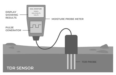
TDR Soil Moisture Sensors (Time Domain Reflectometry)
Time Domain Reflectometry (TDR) sensors emit electromagnetic waves into the soil. The sensor measures the time it takes for these waves to travel through the soil and reflect back. The soil's moisture content is inferred based on this travel time, as water affects the propagation speed of electromagnetic waves: slower waves indicate more moisture, while faster waves suggest drier soil.
The principle can be visualized by analogy: imagine throwing a stone into a lake. The time it takes for the ripples to return to the shore depends on the water's depth. Abundant water (wet soil) slows the ripples, while scarce water (dry soil) allows them to travel faster. TDR sensors measure the return time of these "ripples" to estimate soil moisture.
Advantages of TDR Sensors:
- High Accuracy: TDR sensors typically offer measurement errors within 1%, providing highly precise readings compared to capacitive, resistive, and FDR sensors.
- Fast Response: Measurement data is usually available within 1 second due to the near-light-speed propagation of electromagnetic waves.
- High Durability: The electrodes do not directly contact the soil, and the measurement method doesn't rely on degrading electrical components, ensuring higher durability and stable long-term measurements. Typical lifespans are 5-10 years.
- Compatibility: TDR sensors support various digital interfaces like RS232 and RS485, facilitating easy integration and remote monitoring for high-precision agricultural, soil, and environmental monitoring systems.
Disadvantages of TDR Sensors:
- High Cost: The manufacturing cost of TDR sensors is substantial, making them potentially impractical for small projects or low-budget farms.
- Complex Installation: Installation can be intricate, especially for large-scale measurements requiring precise wiring and techniques.
- High Hardware Requirements: TDR sensors necessitate sophisticated hardware systems and high-performance data acquisition devices, increasing both system cost and technical complexity.
- Regular Calibration and Maintenance: To maintain accuracy, TDR sensors must be regularly calibrated.
Suitable Soil Environments for TDR Sensors:
- Homogeneous Soil: TDR sensors perform best in uniform soils; soil gaps can lead to measurement errors.
- Low Salinity Soils: They are ideal for low to medium salinity soils, being less affected by salinity than other sensor types.
- Moist Soil: TDR sensors are highly responsive to moisture variations in wet soils.
Applications of TDR Sensors:
- Precision Agriculture: Critical for precision agriculture where irrigation must be adjusted based on highly accurate soil moisture data. Accurate moisture information can also help reduce fertilizer and pesticide use.
- High-Precision Irrigation: Essential for high-value crops like vineyards and greenhouse fruits and vegetables, where precise soil moisture control is vital during critical growth stages.
- Scientific and Environmental Monitoring: Used in ecological research, climate monitoring, and soil studies where even minor variations in soil moisture are significant.
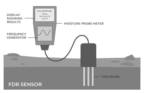
FDR Soil Moisture Sensors (Frequency Domain Reflectometry)
Frequency Domain Reflectometry (FDR) sensors measure the resonance frequency in an electrical circuit during soil moisture detection. The amount of water in the soil influences this frequency, with higher moisture levels causing greater frequency changes. FDR sensors are generally lower-cost and faster than TDR sensors.
An analogy for FDR sensors: tapping a water-filled bathtub produces different frequencies depending on the water level; higher water levels result in lower frequencies. Similarly, FDR sensors detect these frequency shifts to determine soil moisture levels, offering shorter measurement times.
Advantages of FDR Sensors:
- High Accuracy: Typically within 2%-4% accuracy, FDR sensors offer higher precision than resistive and capacitive sensors, especially after calibration, making them suitable for most agricultural scenarios.
- Lower Cost: Compared to TDR sensors, FDR sensors have a simpler structure and lower manufacturing costs, making them more economical for large-scale use, though more expensive than resistive and capacitive sensors.
- Fast Response: Stable data is usually obtained within a few seconds, faster than resistive and capacitive sensors, though not as fast as TDR.
- Salt Sensitivity: Less affected by salt content, making them suitable for high-salinity environments.
Disadvantages of FDR Sensors:
- Sensitive to Soil Homogeneity: Highly affected by soil uniformity. Stones, air gaps, or uneven soil structures can impact measurement accuracy.
- Requires Regular Calibration: To maintain accuracy, regular calibration is necessary, particularly after extended use.
- Limited Measurement Depth: Typically designed for shallow measurements, making them best for monitoring surface soil moisture rather than deeper layers.
Suitable Soil Environments for FDR Sensors:
- Moderate to Low Salinity Soils: Less sensitive to salinity, making them suitable for soils with moderate to low salt content, including saline-alkali or coastal environments.
- Moist Soils: Perform well in moist conditions, responding quickly to moisture changes, ideal for irrigation monitoring.
- Surface Soil: Suitable for monitoring moisture in the topsoil layers.
- Uniform Soils: Best suited for uniform or stable soil structures. Gaps or stones may affect measurements, requiring more frequent calibration in complex soil types.
Application Scenarios for FDR Sensors:
- Large-Scale Agricultural Irrigation Management: More cost-effective than TDR for large-scale applications requiring frequent soil moisture monitoring and irrigation adjustments.
- Large Area Water-Saving Irrigation Systems: Perform well in both moist and dry soils, accurately monitoring moisture levels to optimize irrigation timing.
- Scientific and Environmental Monitoring: Useful in ecological research, climate monitoring, and soil studies where precise soil moisture variations are significant.
Comparison Table of Soil Moisture Sensors
| Sensor Type | Accuracy | Response Time | Durability | Maintenance Frequency | Price | Ease of Use | Suitable Soil Types | Suitable Use Scenarios |
|---|---|---|---|---|---|---|---|---|
| Capacitive | Moderate (±3%-5%) | Moderate (5-10s) | High | Low | Low to Moderate | Easy to Use, suitable for DIY | Ordinary agricultural soils | Smart agriculture, horticulture, hydroponics |
| Resistive | Low (±5%-10%) | Slow (≥10s) | Low (electrodes corrode easily) | High (requires regular replacement) | Lowest | Very easy to use | Suitable for moist environments, but salinity may affect accuracy | Indoor plants, short-term monitoring |
| FDR | High (±1%-3%) | Fast (1-3s) | Moderate | Moderate | Higher | Relatively easy to use, but requires calibration | Common agricultural soils | Large-scale agriculture applications |
| TDR | Highest (±1% or less) | Fast (~1s) | High | Low | Highest | Complex, requires professional handling | All soils | Precision agriculture, research, soil moisture monitoring |
Understanding Soil Water Content and Tension
Soil moisture sensors can be categorized based on the property of soil they measure:
- Sensors measuring volumetric water content (VWC): This refers to the volume of liquid water per unit volume of soil, typically expressed as a percentage. VWC measurements are essential for calculating soil water depletion and scheduling irrigation. For example, a 25% VWC means 0.25 cubic inches of water per cubic inch of soil.
- Sensors measuring soil tension: This indicates the energy required by plant roots to extract water from soil particles. As soil water is depleted, soil tension increases. Soil tension is expressed in centibars (cb) or bars. When soil is saturated, tension is near zero.
Volumetric Water Content (VWC) Calculations:
VWC can be used to determine soil water depletion for irrigation scheduling:
Soil water depletion/deficit (inches) = soil water content at field capacity (inches) - current soil water content (inches)
Note: %Soil water content measurements must be multiplied by the depth of the root zone to obtain total water in that depth. For instance, a 12-inch soil profile with a VWC of 9% contains 1.08 inches of water (0.09 x 12 inches).
Soil Water Deficits and Crop Stress:
Most crops begin to experience stress when soil water depletion reaches 30-50% of the available water holding capacity (AWC). This point is known as the management allowable depletion (MAD) or irrigation trigger point. MAD can vary depending on the crop, its growth stage, and the irrigation system's pumping capacity.
Field Capacity (FC) and Permanent Wilting Point (PWP):
Field capacity is the amount of water a soil can hold after excess water has drained away. It can be measured in the field by observing VWC measurements 12-24 hours after heavy irrigation or rain. The permanent wilting point (PWP) is the soil moisture level at which plants can no longer extract sufficient water and wilt permanently.
Sensor Installation and Placement
Proper installation and placement are crucial for accurate soil moisture sensor readings:
- Multiple Depths and Locations: Sensors should be placed at several depths and locations within a field, typically in pairs at one-third and two-thirds the depth of the crop root zone, and at two or more representative locations.
- Soil Type Management: In fields with varying soil textures, each soil type should be monitored and managed separately. Field mapping technologies can help identify different soil types for creating management zones.
- Placement Within Rows: Stationary sensors should be placed between plants within a crop row at their desired depths.
- Protection: Flag sensor locations to prevent damage from field equipment. Avoid installing sensors close to pivot wheel tracks.
- Direct Soil Contact: Ensure the sensor is in direct contact with the soil, with minimal disturbance during installation.
Installation Methods:
- Digging a Hole/Trench: Sensors can be installed horizontally at different depths.
- Auger/Probe: A hole can be bored using an auger or soil sampling probe for vertical sensor installation.
Care must be taken to avoid oversized holes, which can create voids and air gaps.
Data Logging and Usage:
- Data Loggers: Use data loggers to store and log sensor data, aiding in interpretation and decision-making.
- Integration with Tools: Combine soil moisture data with irrigation scheduling tools like the checkbook method or daily crop water use data.
- Reading Frequency: Read sensors every two to three days.
- Irrigation Strategy: Always irrigate to replenish soil moisture to less than field capacity, allowing room for potential rainfall. Consider pumping capacity and application efficiency when scheduling irrigation.
DIY Soil Moisture Sensor Projects
Many DIY projects utilize common microcontrollers like Arduino and Raspberry Pi to build custom soil moisture sensing systems. These projects often focus on specific sensor types, such as resistive or capacitive sensors, and demonstrate how to integrate them with visual indicators (LEDs) or wireless connectivity for data logging.
Example: Resistive Soil Moisture Sensor with Arduino
A common DIY project involves interfacing a resistive soil moisture sensor with an Arduino UNO. This setup typically includes:
- Resistive Sensor Module: Consists of probes and a module with an LM393 comparator chip.
- Arduino UNO: For processing sensor data and controlling outputs.
- Wiring: Connecting the sensor's VCC, GND, AO (analog output), and DO (digital output) pins to the Arduino.
The project demonstrates how to read analog values to estimate moisture percentage and use the digital output for a simple wet/dry indication.
Calibration for Resistive Sensors:
Calibrating a resistive sensor involves measuring its output in completely dry and completely wet soil. These values serve as reference points to map future readings onto a percentage scale (0% for dry, 100% for wet). The analog reading is inversely proportional to the soil moisture level.
Digital Output for Thresholding:
The digital output pin (DO) can be used to trigger an action when a certain moisture threshold is reached. A potentiometer on the sensor module allows adjustment of this threshold. For example, a green LED can indicate wet soil, while a red LED indicates dry soil.
Advanced DIY: Capacitive Sensor with ESP32
More advanced DIY projects might use a capacitive sensor with an ESP32 microcontroller for features like WiFi connectivity, cloud data logging, and low-power battery operation. The ESP32's touch GPIO inputs can be used directly for capacitive measurements, simplifying the hardware design. Such projects aim for long battery life (e.g., over a year) and compact designs.
How to make Automatic Plant Watering System using Arduino UNO and Soil Sensor || Techie Lagan
Key Considerations for Choosing a Soil Moisture Sensor
When selecting a soil moisture sensor, consider the following:
- Application Requirements: Precision agriculture demands high accuracy (TDR), while home gardening might suffice with moderate accuracy (capacitive) or low cost (resistive).
- Soil Type and Salinity: Some sensors are more sensitive to soil salinity and homogeneity than others.
- Durability and Maintenance: Direct contact electrodes (resistive) corrode faster than non-contact designs (capacitive, TDR, FDR).
- Cost: Resistive sensors are cheapest, followed by capacitive, FDR, and TDR sensors.
- Data Logging and Integration: Compatibility with microcontrollers and data logging systems is essential for automated monitoring and analysis.
While resistance-based sensors are inexpensive and easy to integrate into DIY projects, their accuracy is limited by soil type and salinity. Dielectric-based sensors (TDR, FDR, capacitance) offer superior performance, with their effectiveness often depending on installation quality, measurement frequency, and circuit design.